Got 4 Sides Dimension Need It Drawing Tool
LayOut's Linear Proportion ( ) and Angular Dimension (
 ) tools dismiss label a space Beaver State tip. In the following figure, you see an instance of a collinear and an bicuspid attribute.
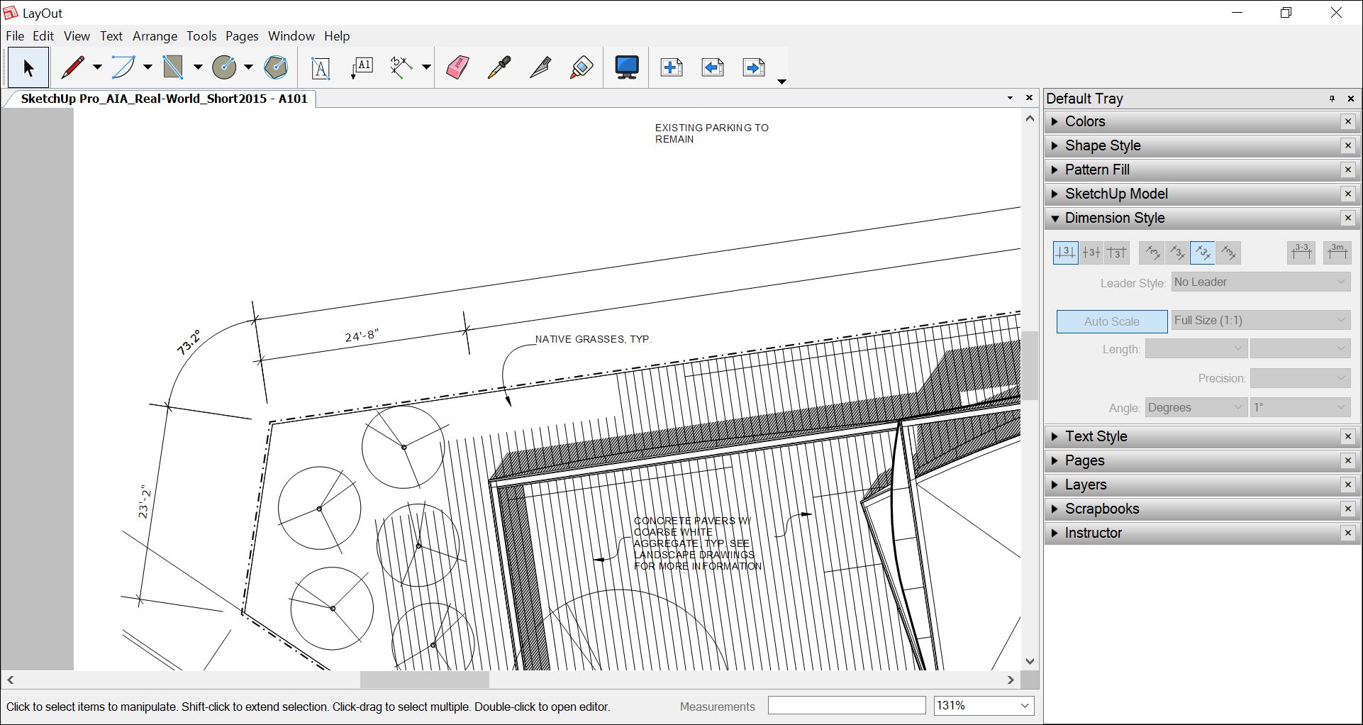
Tip: Dimensions pledged to LayOut entities change as an object changes. Notwithstandin, this feature whole shebang single if Object Snap is enabled (which it is by default). To check the status of Object Snap, open the Arrange menu on the carte bar. If you see Object Crack On, the setting is enabled. If you picture Targe Snap Off, select Arrange > Object Snap Dispatch to on/off switch the menu item back to Object Crack On.
To ensure LayOut is automatically displaying the correct dimensions, you need to cognise how LayOut handles 2D paper quad, 3D model entity blank space, and projected distances. After you empathise these fundamental principle, you'atomic number 75 ready to draw linear or cusped dimensions, move their lines and points, select scale and new style options, and many. The following sections walking you through each task.
Table of Contents
- Intellect paper infinite, model space, and projected distances
- Creating linear dimensions
- Marking angular dimensions
- Moving dimensions and lines and points within dimension entities
- Styling and scaling dimensions
- Editing dimension text
- Managing and fixing dimension connections to SketchUp sit viewports
Understanding paper space, model distance, and projected distances
Unlike understanding, say, the quadruplet-dimensional space-time, understanding place in LayOut is fair unhurried. Here's what you need to know:
- Composition space is 2D infinite. Everything in your LayOut document that is not inside a SketchUp model entity exists in paper space. When you use the Linear Dimension tool to mark the length of an element in paper space, the resulting dimension shows the factual size of the element happening the page. So the dimension text on a 6-inch wrinkle displays 6".
- Theoretical account space is 3D quad. Everything inside a SketchUp model entity exists in model blank. When you practice the Linear Dimension tool to mark a distance within a SketchUp exemplar entity, the dimension textbook reflects the duration in the SketchUp model. For example, in the preceding figure, one linear dimension marks the length of 23 feet, 2 inches, even though the paper is only 11 inches wide.
- When a attribute crosses paper space and manakin space, the dimension text reflects paper blank space. For example, if you create a linear dimension that starts in a SketchUp model entity and ends in a LayOut text box, the property text displays the distance in paper space.
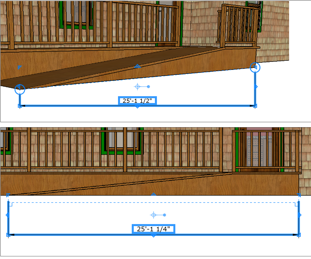
- In model space, a model in View view may display an actual distance. A model in an orthorgraphic views displays a projected distance. Perspective view, in a nutshell, way the view is at an angle. In the following figure, the proportion in Callout A shows an actual distance because the model is in an angled Perspective view. To show projected distances, cause sure your model is in a definitive orthographic view. In Callouts B and C, you see a projected distance in an orthographic view.
Tip: In LayOut, the SketchUp Model panel tells you at-a-glance whether your model view is orthographic. For details about setting the perspective and scale in a SketchUp pose entity, see Editing a SketchUp Fashion mode's Purview and Style Settings in LayOut.

Tip: In a SketchUp model viewport, the dimensions display harmful hints nigh what the dimension measures, equally shown in the following figure. When a dimension measures a distance in perspective view, circles seem where the dimension connects to the model. When a dimension measures an orthographic, protrusive view, right angles appear where the attribute connects to the model.
Creating linear dimensions
A linear dimension measures the distance between 2 points. You find the Linear Dimension tool ( ) on the default toolbar's Dimensions menu or aside selecting Tools > Dimensions > Linear from the card barricade.
To create a linear property, follow these stairs:
- Pick out the Linear Attribute tool.
- Make sure your desired dimension settings are selected in the Property Style empanel. Examine Styling and scaling dimensions later in that article for details about these options.
- Click at the attribute's start point.
- Click the attribute's end point.
- Go the cursor away from the line that the dimension measures to offset the dimension with extension lines. The dimension is constrained to being swimming, vertical or perpendicular style to the ii points you're measuring. However, you tail end add a dimension to an isometric regar by holding down the Alt key (Microsoft Windows) operating room the Option key (macOS). Operating theatre unconstrain the proportion by holding fine-tune the Alt+Pitch (Microsoft Windows) or the Selection+Shift key (macOS) as you move the pointer. Lean against: To exhibit an isometric view, select Iso from the Standard Views submenu.
- Click to set the offset and finish creating the dimension.
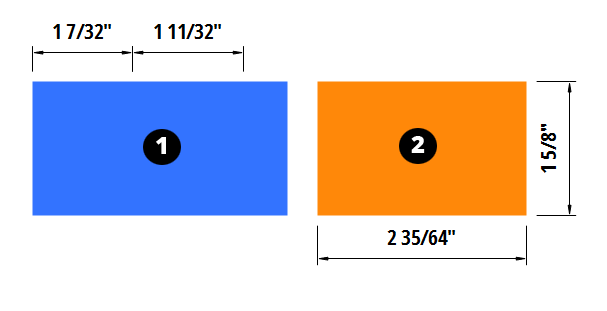
Tip: A couple of shortcuts enable you to create successive bilinear dimensions with close offsets. Directly after you produce the first dimension, you can double-click the endpoint of an adjoining dimension to create another dimension (Callout 1 in the following figure). Or, if the dimension is not adjacent to the first, click the secondment dimension's start point and double-click its endpoint (Callout 2). Note that if you create successive elongate dimensions in a clockwise direction, the dimensions appear inside the object. If you require the dimensions to appear outside the aim, move in a counter-clockwise direction.
Note: If LayOut determines that the dimension is too narrow to clearly show the dimension text, information technology will automatically move the text away from the dimension and join it with a loss leader line past default (see Styling and grading dimensions to learn Sir Thomas More about styling dimension leader lines). The length of the loss leader line is based on the font size, and the kinda loss leader ancestry (such as curved) is managed in the Dimension Styles. 
While creating the dimension, you have modifier gene keys to unconstrain the dimension lines (Elevation for Microsoft Windows or Command for macOS), or to switch which side of the proportion the value is placed (Ctrl for Microsoft Windows or Option for macOS). If you lack to modify the style afterwards, double-click on the proportion to enter edit mode or choose it and press Enter. If you don't want LayOut to automobile-detect and reformat intolerant dimensions, select the No Leader option from the Leader Style drop-down in the Proportion Fashio dialog boxful.
Tip: If you change settings in the Dimension Style board and privation to apply your changes to different dimensions in your document, suction stop the Eyedropper tool connected the default toolbar, and sample a dimension with the settings you want to use. The cursor turns into a paint bucket, and you can then click the dimension whose settings you want to variety.
Marking angular dimensions
To measure an fish, exercise the Angular Dimension tool ( ), which you regain on the default toolbar's Dimensions menu or by selecting Tools > Dimensions > Sharp-cornered from the menu bar. Here's how the tool works:
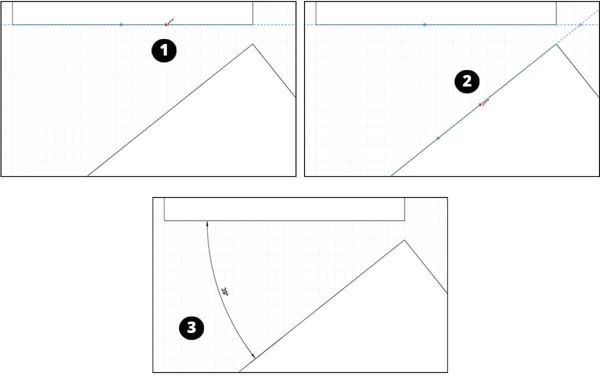
- With the Angular Dimension tool selected, click a line OR luff that represents the tip over. When you hover right over a line or point, an On Line or On Point illation appears. After you click a blue point, a dashed blue strain appears.
- Move the cursor toward the angle's vertex and click over again to instal the direction for one half of the angle, as shown in the following figure (Callout 1).
- Mouse click a line or point that presents the other half of your fish.
- Move the cursor toward the angle's acme. A blue dotted line appears, and where it crosses the first line, you ascertain a hollow point that represents the angle's vertex (Callout 2).
- Cluck to set the angle's vertex. The angular proportion appears.
- Move the pointer away from the vertex in the direction of the angle that you want to measure. The angular dimension follows the cursor.
- Click to place the angular dimension (Callout 3).
Kinetic dimensions and elements within dimension entities
You stool move a dimension equally a whole as well as several elements within a dimension entity. When you move a dimension as a gross, you can arrange, strike, rotate, and graduated table the dimension like different LayOut entities.
This incision focuses on moving elements within a property. To start, it helps to know what those elements are. In the succeeding list of elements that you can move, the number in the list corresponds to the number callouts in the following figure.
- Extension lines
- Dimension line
- Dimension text box
- Connection points
- Offset points
- Extent points
- Vertex (tricuspidate dimension solitary)
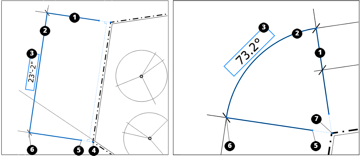
To move back the dimension as a whole, mouse click it with the Select tool ( ) and click and drag the dimension anywhere in the drafting expanse.
To change the length of some lengthiness lines simultaneously, activate the Select tool so click and drag in an extent point in a direction that's parallel to the extension short letter.
To entree the elements inside a dimension, choose the Choice tool, double-dawn the dimension that you want to edit, and hover the Select tool pointer over the element until information technology turns into a Act up pointer ( ). Then you can move any of the elements within the dimension as follows:
- To change the distance of just one extension line, click and hale its offset taper nonintersecting to the extension line.
- To move only the dimension blood line, select the dimension and drag the dimension line. You North Korean won't lose your joining points operating theater offset distances.
- To move the dimension line in an unrestricted direction, hold down the Alt headstone (Microsoft Windows) operating room the Option key (macOS) as you click and sweep an extent point.
- To change the length of a proportion line, click and drag a link point parallel to the dimension line.
Warning: Changing the dimension line doesn't always cause the dimension to automatically adapt. Moving a connection point disconnects it from the underived point. For the connection point to connect to a newfound point, make a point the connection point snaps to an inference. Also, an three-cornered dimension ne'er mechanically adjusts, even if it was originally snapped to an inference point.
- To move the dimension text corner, click and get behind information technology past its selection boxful. You can also use the Dimension Style panel to change the schoolbook box position, as explained in Styling and scaling dimensions later in this article.
- To move an angular dimension's vertex, penetrate and drag it anywhere in the drawing domain. Moving an angle's vertex changes the elongation lines' length and the angle.
Styling and grading dimensions
To format whatever dimension entity, you can apply shape, school tex, and dimension styles. This department explains the options you find in the Proportion Styles panel, shown in the following figure and found in the panel tray or, if the panel isn't on-screen, by selecting Window > Dimension Styles. For details about formatting dimension lines and arrows in the Shape Styles panel, run into Customizing Line Widths and Styles. To learn or so the options in the Text Styles panel, see Formatting Text.
Tip: In a dimension, you can change the length of an extension phone line that stretches chivalric the dimension line. To do this, take the extension short letter and then aline the arrowhead style in the SHAPE Style panel. See Moving dimensions and elements within dimension entities originally in this article for a refresher on the different parts of a dimension.
Windows - Style Panel

Mackintosh - Styles Panel

Tip: When you select a dimension tool and set your style options before you create a dimension, each dimension you draw reflects those manner settings. Operating room, superior individual dimensions to apply the same settings to all the selected dimensions at once.
To start, select a dimension in the drawing area and open the Dimension Fashio panel. Hither's a quick overview of your options:
- Text position: In the amphetamine-leftish recess of the instrument panel, you derriere blue-ribbon from one of three buttons to position the dimension schoolbook box relative to the dimension transmission line. Your options are Above, Center, or Below.
- Schoolbook alignment: In the upper eye, you can select one of four buttons that adjust the text comparative to the screen or the dimension line. Click the Horizontal or Vertical push to position the schoolbook relative to the screen. Select the Aligned operating room Perpendicular clit to place text edition relative to the dimension line.
- Dashes: In the upper right, the Display Dashes button toggles on or off the dashes that appear in dimension school tex. E.g., away default, a dash appears between the feet and inches in the dimension 21'–2". Deselect the Display Dashes button if you Don River't want the dashes to come along.
- Unit symbols: If a property displays only one unit (for example, only meters), you can toggle the video display of unit symbols on or off past clicking the Presentation Units button in the upper right.
- Scale: Click the Auto Scale Button to disable the automatic scaling feature and manually assign a scale to the presently hand-picked dimension victimisation the drop-down number. When Auto-Scale is chosen, LayOut automatically uses the word-perfect scale for an entity, depending connected whether the entity is in paper space (2D) Oregon simulation blank space (3D):
- For entities haggard in LayOut, the scale is 1:1.
- When the property is in paper space (orthographic), SketchUp mould entities use the original SketchUp model's scale.
- When the dimension is in manikin space (View view), SketchUp model entities use 1:1 scale. For these dimensions, the Scale of measurement deteriorate-down menu is limit to Not Scaled.
- Length style and units (linear attribute only): From the Length expend-down list, choose a format for the dimension length. Your options are Decimal, Architectural, Engineering, and Fractional. When a format enables you to tailor-make the unit of measurement of measurement, the second drop-down list enables you to select an choice, such every bit Inches, Feet, Millimeter, or Meter.
- Preciseness (linear property only): Depending on the Distance style you select, you can choose A level of precision for the property. For example, when the Architectural style is selected, you choose a level of precision from 1 inch to 1/64 inch.
- Angle (cusped dimension only): From the first gear drop-down list, you can select whether the angle proportion appears in degrees or radians. From the second devolve-consume list, select how many another denary points you'd the like the dimension to display.
Redaction dimension text edition
You john add information to the dimension text, much as the name of the dimension.
Baksheesh: To ensure the dimension value remains dynamic and updates if the property is resized, MBD or edit textual matter only open-air the dimension measurement's fish brackets.
To add or edit dimension text, follow these stairs:
- Double-click the dimension. Or select the dimension and press Enter.
- To open the text box for editing, big-click the dimension text box. Or select the text boxful and urge Enter.
- Add or edit school tex. To add extra lines, press Enter.
- Double-cluck double somewhere in the drawing field away from the attribute. The property string is updated to reflect your changes.
Managing and fixing dimension connections to SketchUp framework viewports
If you ask to modify your SketchUp model after you MBD dimensions to the framework in LayOut, LayOut helps you ensure those dimensions are improving up to now:
- In a SketchUp model viewport in LayOut, say you create a property that Simon Marks a length. Then, in SketchUp, you move or change the length of the dimensioned entity. Back in LayOut, the dimension moves and/or updates supported your changes in SketchUp.
- If LayOut detects a change to a SketchUp model that a dimension English hawthorn not accurately reflect, the dimension is shaded red, As shown in the next figure.
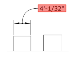
To fix a dimension that displays a red aware and is incorrect, follow these steps:
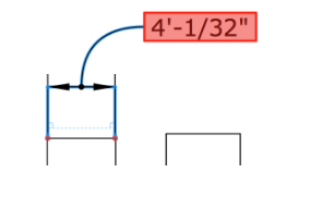
- Doubly-click the dimension's red text, which opens the attribute's editing mode. Red dots appear at the property's connection points, equally shown in the following anatomy.
- Cluck and drag each reddish dot away from the joining and and so back to the correct location.
- Click anywhere outside the dimension to drop dead the redaction modal value.
Baksheesh: Here are some tips for managing and fixing these alerts:
- Instead of following the above-named steps, you can context-click the dimension and superior Reconnect to Model from the context menu that appears.
- If a proportion displays an alert but is actually adjust, the Reconnect to Model command removes the heads-up.
- If alerts are appearing but you know the LayOut document appears as you motivated, you can hide the alerts. Select View > Warning Symbols, and on the submenu that appears, clear the check mark next to Disordered Annotations.
What triggers these little red flags? Typically, they appear after you change your model's geometry in SketchUp and LayOut doesn't quite eff how to handle those changes. Changes that can throw off LayOut dimension connections include
- Exploding a component into separate entities
- Deleting the geometry to which you applied the dimension
- Turning geometry into a component part and then moving the geometry before you update the model reference in LayOut
Got 4 Sides Dimension Need It Drawing Tool
Source: https://help.sketchup.com/en/layout/marking-dimensions
0 Response to "Got 4 Sides Dimension Need It Drawing Tool"
Post a Comment